Acousto-optic Modulator for High-power Pulsed Fiber Laser
Acousto-optic Modulator for High-power Pulsed Fiber Laser
Abstract:
The present invention relates to an acousto-optic modulator for high-power pulsed fiber lasers, including an input pigtail, a collimating lens, an acousto-optic device, a focusing lens, and an output pigtail. The input pigtail is placed at 3.7° with the horizontal plane, and the output tail The fiber and the horizontal plane are placed at 0° or 3.7°, the input pigtail and collimating lens are installed together to form an input fiber collimator, and the output pigtail and focusing lens are installed together to form an output fiber collimator, and then the input, The output fiber collimator and the acousto-optic device are assembled as a whole; a narrowband filter can be placed between the acousto-optic device and the output fiber collimator, and the input fiber collimator and output fiber collimator can be combined into one Fiber collimator, add a narrow band high reflector. The invention effectively improves the mechanical stability of the laser system, can effectively suppress the nonlinear effect in the doped fiber, and realizes high-power, narrow-spectrum pulsed laser output by coating different components.
Background technology
Q-switched double-clad fiber lasers have many advantages such as low price, compact structure, high efficiency, narrow line width, tunable wavelength, etc., in many fields such as remote sensing, ranging, medical, military, industrial processing, nonlinear optical applications, etc. Widely used.
At present, the commonly used method to obtain high-power pulses through double-clad fiber is that the main oscillator provides a "seed" pulse, and then injects it into the double-clad fiber amplification (M0PA) to obtain it. The seed oscillator (M0) often uses a mode-locked laser or Traditional Q-switched solid-state lasers [see Prior Art: CLE02002, CThX3, 591]. A simpler method is to insert a Q-switched device directly into the double-clad fiber laser cavity to obtain high peak power and high energy lasers. Pulse [see Prior Art: CLE02003,626]. Although the above two methods can obtain high-power pulsed laser output, it is not easy to realize the full fiber laser of the laser.
In order to realize the full fiberization of the fiber laser, one method is to use a modulated semiconductor laser as the M0 in the M0PA structure, that is, a multi-stage fiber amplification structure [see Prior Art: Opt. Lett., 30 (24), 2005, P3299] . The disadvantage of this method is that the output power of the seed source is small, and multi-stage amplification is required to achieve the required power, and an optical isolator is required before each stage of amplification, which easily produces nonlinear effects in the fiber, which limits its output power. The further increase, and the cost is higher. Another method is to insert a pigtailed Q-switched device into the double-clad fiber laser cavity. This method also realizes the full fiberization of the laser, making the laser more compact, but it is easy to carry at high power. The new problem of self-excited oscillation in the cavity also limits the further increase of laser power.
The purpose of the present invention is to overcome the above-mentioned problems in the prior art and provide an acousto-optic modulator for high-power pulsed fiber lasers. The acousto-optic modulator of the present invention has pigtail input and output, which can easily realize the All fiber optic. Corresponding treatment of the end face of the pigtail can suppress the self-excited oscillation in the doped fiber, so as to achieve high-power pulsed laser output, and achieve narrow-spectrum laser output by coating different components.
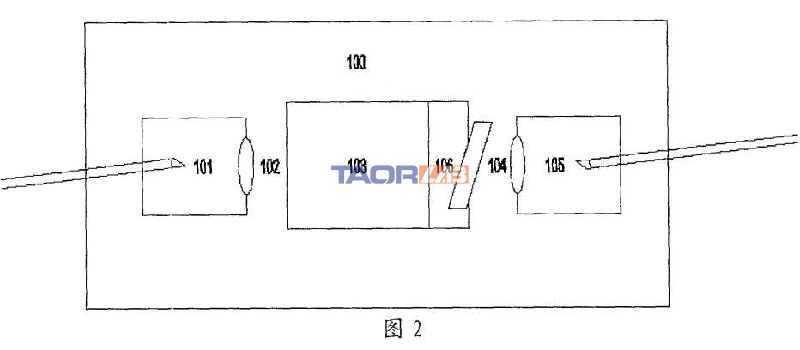
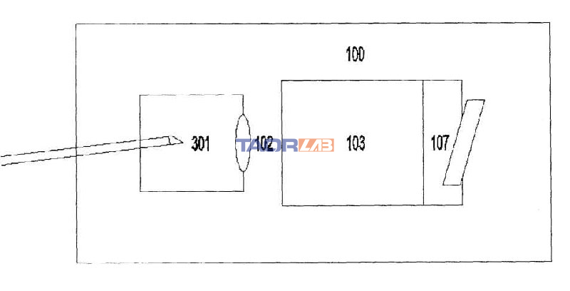
The structure of the acousto-optic modulator for high-power pulsed fiber lasers of the present invention is shown in Figure 1, Figure 2 and Figure 3.
Acousto-optic modulator for high-power pulsed light, including input pigtail 101, collimating lens 102, acousto-optic device 103, focusing lens 104 and output pigtail 105. Input pigtail 101 is placed at 3.7° with the horizontal plane, and output The pigtail 105 is placed at 0° to the horizontal plane, the input pigtail 101 and the collimating lens 102 are installed together to form an input fiber collimator, and the output pigtail 105 and focusing lens 104 are installed together to form an output fiber collimator, and then the input The fiber collimator, the output fiber collimator, and the acousto-optic device 103 are assembled as a whole 100. The input pigtail 101 and the output pigtail 105 are fused with fiber end caps and each ground into an oblique 8° plane, and A broadband antireflection film is plated on the oblique 8° plane of the input pigtail 101, and a narrowband transmission film is plated on the oblique 8° plane of the output pigtail 105. As shown in Figure 1.
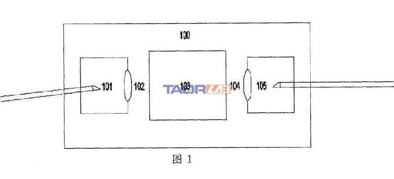
The acousto-optic modulator of another structure of the present invention is shown in Fig. 2. The input pigtail 101 is placed at 3.7° with the horizontal plane. The input pigtail 101 and the collimating lens 102 are installed together to form the input fiber collimator. The ends of the fiber 101 are fused with fiber end caps and each ground into an oblique 8° plane, and a broadband anti-reflection coating is plated on the oblique 8° plane. The output fiber formed by the acousto-optic device 103, the output pigtail 105 and the focusing lens 104 is collimated A narrow-band filter 106 is placed between the devices, and the output pigtail 105 is placed at 3.7° from the horizontal plane. A broadband anti-reflection coating is plated on the oblique 8° plane of the output pigtail 105. The acousto-optic device 103 and the narrow-band filter 106 are installed together. , And the narrow-band filter 106 and the first-order diffraction direction of the acousto-optic device 103 are placed at a corresponding angle, so that the narrow-band filter 106 has the maximum transmittance to the set wavelength, and cannot reflect other wavelengths of light back to the acousto-optic The device 103 enters the input fiber collimator, and then the input fiber collimator, the output fiber collimator and the acousto-optic device 103 and the narrowband filter 106 are assembled as a whole 100.
Another structure of the acousto-optic modulator of the present invention is shown in Figure 3. The input pigtail and output pigtail are combined into a pigtail 301, the focusing lens 104 is removed, and a narrow-band high reflector 107 is added. The pigtail 301 is connected to the horizontal plane. Place it at 3.7° and install it with the collimating lens 102 to form a fiber collimator. The end of the pigtail 301 is fused with a fiber end cap and ground to an 8° bevel, and the bevel is plated with a broadband antireflection coating, acousto-optic device 103 And the narrow-band high-reflective mirror 107 are installed together, and the narrow-band high-reflective mirror 107 is perpendicular to the first-order diffracted light through the acousto-optic device 103, and then the two parts are assembled into a whole 100.
The three acousto-optic modulators of the present invention are free of internal adjustment, which greatly improves the mechanical stability of the entire system.
The 1064±0.5nm anti-reflection coating is plated on the 8-degree oblique surface of the output pigtail 105. Only for Yb-doped fiber lasers, the anti-reflection coating of the corresponding wavelength can be selected according to the working wavelength of the doped fiber. The anti-reflection coating is highly transparent to the 1064+0.5nm laser, ensuring that the laser of this wavelength forms an oscillating output in the cavity, and the light of the other wavelengths obliquely has a large reflection loss, thereby narrowing the width of the laser output spectrum.
The narrow-band filter 106 is placed at an angle with the acousto-optic modulator 103, and the surface is coated with a narrow-band transmission film. The narrow-band transmission film of the corresponding wavelength can be selected according to the working wavelength of the gain fiber. For example, the Yb-doped fiber laser is coated with 1064± The 0.5nm narrow-band transmission film ensures that the laser with the set wavelength will form an oscillating output in the cavity, while obliquely facing the light of the other wavelengths has a large reflection loss, thereby narrowing the width of the laser output spectrum.
The surface of the narrow-band high reflection mirror 107 is coated with a narrow-band high-reflection film. The narrow-band high-reflection film of the corresponding wavelength can be selected according to the working wavelength of the gain fiber. For example, for a Yb-doped fiber laser, a 1064+0.5nm narrow-band high-reflection film is coated , Placed perpendicular to the first-order diffraction direction of the acousto-optic device, to ensure that the laser of the set wavelength forms an oscillating output in the cavity, and the light of the other wavelengths has a large transmission loss, thereby narrowing the width of the laser output spectrum.
The invention is an acousto-optic modulator with pigtail input and output, easy to realize all-fiber fiber laser, which effectively improves the mechanical stability of the laser system, can effectively suppress the nonlinear effect in the doped fiber, and can be used in different components The method of coating film to achieve high-power, narrow-spectrum pulsed laser output.
Specific implementation:
As shown in Figure 4, the pigtailed 915nm pumped semiconductor laser 401 is fused to the total reflection fiber grating 402, the total reflection fiber grating is fused to the gain fiber 403, the gain fiber is fused to the input pigtail 404, and the input pigtail is fused to the fiber end The cap is ground into an 8° inclined surface, then a broadband antireflection coating is plated, and it is placed at 3.7° from the horizontal. The laser generated by the gain fiber passes through the input pigtail 404 and the collimating lens 405 to form a collimated beam into the acousto-optic The device 406 generates Bragg diffraction, and the diffracted first-order light is coupled into the pigtail 408 through the focusing lens 407. The output pigtail 408 is fused with a fiber end cap, ground into an 8° bevel, coated with a narrow-band anti-reflection coating, and placed at 0° from the horizontal plane. In this way, only the narrowband wavelength set in the first-order diffracted light is allowed to enter the output pigtail 408, while reflecting other wavelengths, the reflected other wavelengths will not enter the output pigtail through the acousto-optic device, and the output pigtail 408 and part of the The reflective fiber grating 409 is spliced. In this way, the fiber gratings 402 and 409 form a resonant cavity. Because the output pigtail 408 and the oblique 8° surface are coated with a narrow-band anti-reflection coating, the excitation of other wavelengths is suppressed, so that the pulse fiber laser formed in this way has a narrow linewidth output. No nonlinear wavelengths appear. We use this structure to obtain an average output power of 2W at a frequency of 20kHz, a pulse width of 40ns, and a peak power of 2.5kW. Fig. 5 shows the output spectrum of the acousto-optic modulator using the present invention, and comparing it with the spectrum of the same power level generated by the ordinary acousto-optic modulator, it is obvious that the spectrum is broad and has Raman wavelengths.
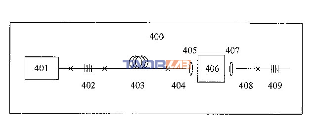
Figure 4: A schematic diagram of a specific embodiment of the present invention.
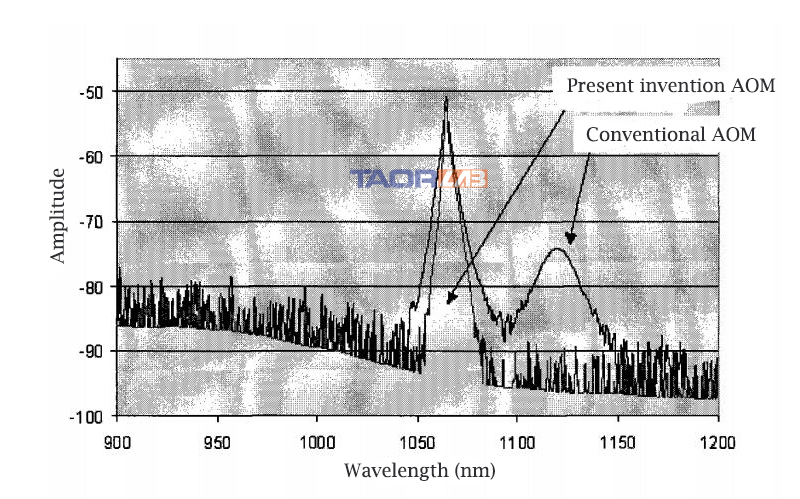
Figure 5: A graph showing whether to use the output spectrum of the acousto-optic modulator of the present invention and comparing the spectrum with the same power level generated by a common acousto-optic modulator.
Comments
Post a Comment